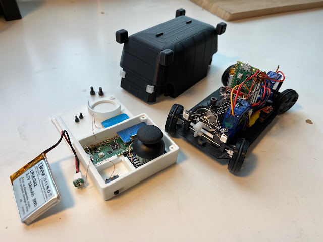
I started working on this project almost two years ago, right after Zoox did its product reveal at the end of 2020. We did a teaser video at Coit Tower in San Francisco and we released a press pack of hi-res photos on our website. I took those photos and used them to create a very low-res and frankly pretty inaccurate CAD model of our vehicle. The initial idea was to make a full-featured remote control car, but it was obvious that that would take me a while and I wasn't suffering from an excess of free time. There wasn't any easy way to complete this if I wanted my toy to act anything like the real Zoox vehicle. Zoox has four-wheel steering, which means I couldn't just print out a new body and plop that on top of an off-the-shelf RC car. On top of that Zoox's vehicle drives forward and backward. And because its front and rear steering are independent, it can drive diagonally. So this toy would need to be built from scratch.
Two years later, it's done. I squashed together a bunch of hobby MCUs, servos, motors, batteries, and radios to produce a remote-control car that has bi-directional driving and multiple four-wheel steering options. I'm pretty happy with the results.
Mechanical
This was the most time consuming part. I went through sooooo many prototypes to get the four-wheel steering working. Most RC cars have front wheel steering and rear wheel drive. And this is really easy to implement. But I needed all four wheels to move and then still drive at least two of them, so I have to transmit power through a steering system. And this is hard to do on a vehicle where the wheels are one inch diameter. My first successful design involved lots of crown gears and way too many parts overall. I ditched that and spent a while actually printing and assembling the smallest double-universal joints I've found, 2.6mm diameter for a 1mm shaft. That was a miserable experience so I ditched that as well. After that I tried using a thin wire rope as a flexible shaft, but even using a 0.032" rope it still had too much internal friction when bent +/-10º, and the hobby servos had trouble bending it that far. Finally I settled on adding a single universal joint to each wheel. This means I have a bit of wobble when driving with the wheels turned all the way, but I can live with that.
In parallel with figuring out power transmission, I had to figure out speed reduction. I needed somewhere between a 10:1 and 20:1 reduction from the brushed DC motor to the wheels. Originally I printed some worm and helical gears, but being as tiny as they were they were poorly shaped and just didn't turn reliably. No amount of sanding, filing, and lubricating helped. I can print perfect spur and helical gears, but I've never found a way to print decent tiny worm gears. Maybe someday I'll buy an SLA printer for that occasional ultra-tiny part, but not today. Next I went with a 4:1 x2 spur gear reduction, which worked great but was enormous and stuck out the sides of the vehicle. I ended up buying hobby gears for $5 that are made from PTFE and work perfectly. I could have saved tens of hours of work by just spending $5 at the beginning.
Steering was just a simple four-bar linkage driven by a hobby servo. Except there are two of them, one on each end of the vehicle. The servos rotate in opposite directions to provide four-wheel steering, the front servo moves and the rear servo stays centered for two-wheel steering, and the servos rotate in the same direction for diagonal crab-walk-style motion.
Electrical
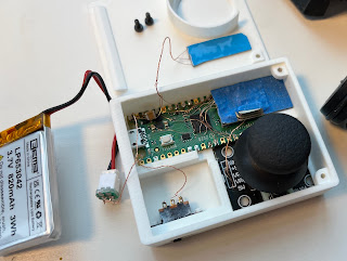
This was time consuming, as EE tends to be, but not particularly difficult. The only major headaches were the multiple times when cheap hobby products didn't perform anywhere near manufacturer's advertised specs or didn't run at all and I spent hours or days trying to figure out what was wrong. Both the controller and the vehicle contain Raspberry Pi Picos, my current favorite hobby MCU, NRF24L01 radios, LIon batteries, and WS2812 LEDs. The vehicle contains two 1S batteries providing 7.4V, two SG90 servos, and one brushed DC motor driven by a TB6612FNG motor driver. The SG90 servos that I bought advertised that they operated with 3-6VDC, but in reality they wouldn't move with less than 4.5V. I charged my batteries when I first received them a month ago and haven't yet had to recharge.
Code
The total code for this project is ~250 lines for the controller and 250 lines for the vehicle. That doesn't include a hobby driver I found for the NRF24L01, for which I am extremely grateful to guser210. There's not much going on, just a while loop on the controller that reads the joystick, updates the LEDs, and publishes commands to the radio. The vehicle has a loop that checks for commands from the radio and then updates the control values for the motor driver, servos, and lights.
Future
I now have one complete and functional toy car. I only need one, so I might end the project here. But I have so many ideas in my head for how #2 could be improved, so we'll see. I might be able to get rid of the universal joints and just put a tiny motor on each wheel. I'd like to cut out the doors and windows from the body shell and fill those with acrylic so you can see through. I'd like to print the body out of an approximately mint-green color, like Zoox's actual vehicles. I'd like to use 2mm shafts throughout instead of the 1mm shafts I used in the first vehicle. I'd like to add functional doors and other lights. I'd like to improve the speed control. I have PWM control of the motor and servos, but currently it seems like they're only ever at zero or max or min. That might be a problem with how I read the joystick on the controller. I should definitely combine all of the various PCBs onto a single custom PCB, instead of connecting everything precariously with magnet wire like I've been doing. And a hundred other small tweaks. But I should probably get back to the rest of my life first.


